Dynafiber
A DWDM transceiver is a network component that sends and receives data over dense wavelength division multiplexing systems. It converts electrical signals into optical signals, then places them on specific wavelengths within a single fiber. On the receiving side, it performs the reverse operation.
This process allows many independent data channels to share one optical path. Each channel uses a carefully spaced wavelength, often called a channel frequency. A multiplexer combines these wavelengths before transmission. At the far end, a demultiplexer separates them again. The DWDM transceiver must maintain accurate wavelength control, stable power, and reliable signal quality across long distances.
In a data center, the device may connect to a router through a high-speed electrical interface. Its optical port then sends light through a dense fiber cable. The result can resemble several colored beams traveling along one strand, although the wavelengths are invisible to the human eye. Engineers monitor parameters such as transmit power, receive sensitivity, temperature, and dispersion.
Performance depends on more than the transceiver alone. Fiber condition, amplifier settings, connector cleanliness, and network distance also matter. A specification sheet may look convincing, yet field results can differ. That is why experienced technicians verify compatibility through testing and diagnostic data. This article explains the operating principles, key components, common formats, and practical selection criteria behind a DWDM transceiver. The technology is powerful, but not effortless. Small installation errors can reduce an otherwise capable link.
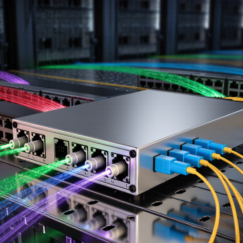
A DWDM transceiver is an optical device used to send and receive data across fiber. It converts electrical signals into light and converts received light back into data. Unlike a basic optical module, it uses a specific wavelength within the fiber spectrum. The “dense” part means many wavelengths share one fiber. Each wavelength acts like a separate traffic lane.
DWDM transceivers increase fiber capacity without installing new cables. At a data center, one module may carry high-speed traffic toward a regional network site. The transceiver sends light through a selected channel, while a multiplexer combines several channels onto one fiber. At the far end, a demultiplexer separates them. Network equipment then reads each signal independently. Small errors matter.
In network operations, engineers verify wavelength settings, transmission distance, power levels, and error performance. They also inspect connector cleanliness and fiber loss, because a tiny contaminant can weaken an optical signal. Some transceivers support tuning across multiple channels, while others use a fixed wavelength. Capacity figures can look impressive, but they depend on fiber quality, line amplifiers, dispersion control, and forward error correction. In real deployments, documentation is sometimes incomplete. That gap can complicate troubleshooting. Careful testing remains essential.
What Is a DWDM Transceiver and How Does It Work?
Key Components Inside a DWDM Transceiver
A DWDM transceiver converts electrical client data into a precise optical wavelength. It also converts received light back into electrical signals. The International Telecommunication Union reported 5.5 billion internet users in 2024. That growth increases pressure on long-distance optical networks.
The transmitter begins with a serializer and clock circuit. These circuits prepare incoming data for high-speed transmission. A laser then generates a stable optical carrier. Its wavelength must fit the planned channel grid. ITU-T G.694.1 defines DWDM frequency spacing, including 50 GHz and 100 GHz options. A modulator impresses data onto the carrier. Temperature control matters here. Small thermal changes can shift the wavelength.
Inside the receiver, a photodiode detects faint incoming light. A transimpedance amplifier strengthens that signal. High-performance modules may use coherent detection and digital signal processing. These circuits correct dispersion, noise, and some polarization effects. The optical connector, monitoring sensors, and control processor complete the module. In field work, clean connectors often matter more than impressive specifications. Dirt causes measurable loss. Not every fault is complex. Power consumption also deserves attention, especially in dense racks. A module may meet its advertised reach, yet perform poorly under heat, aging, or imperfect fiber conditions. That is why engineers verify temperature, optical power, wavelength accuracy, and error rates during commissioning.
| Component or Data Dimension | Primary Function | How It Works in a DWDM Transceiver | Typical Technical Characteristics |
|---|---|---|---|
| Host Electrical Interface | Connects the transceiver to the network device. | Receives high-speed electrical data from a switch, router, or transport system and sends recovered data back to the host. | Common host interfaces include Ethernet or telecom electrical lanes; the exact lane rate depends on the module design. |
| Digital Signal Processor (DSP) | Processes, shapes, and compensates high-speed signals. | Performs functions such as equalization, chromatic-dispersion compensation, polarization processing, carrier recovery, and forward-error-correction processing. | Especially important in coherent DWDM systems operating at 100G, 200G, 400G, or higher data rates. |
| Forward Error Correction (FEC) | Improves the reliability of data transmission. | Adds controlled redundancy at the transmitter so the receiver can detect and correct a limited number of transmission errors. | The coding overhead and correction capability vary by implementation; FEC increases the effective performance margin. |
| Laser Source | Generates the optical carrier. | A narrow-linewidth laser emits light at a selected DWDM channel. In tunable modules, the operating wavelength can be adjusted electronically within a supported band. | The C-band is commonly centered around the 1530–1565 nm region; wavelength accuracy and stability are critical for channel spacing. |
| Optical Modulator | Imprints electrical data onto the optical carrier. | Changes the phase, amplitude, or polarization of the continuous-wave laser according to the transmitted electrical signal. | Coherent transmitters commonly use dual-polarization modulation and formats such as QPSK or higher-order QAM. |
| Wavelength Tuning and Control Circuit | Keeps the transmitter aligned to its assigned grid channel. | Monitors optical frequency and adjusts the laser or resonant elements to maintain the selected wavelength despite temperature and aging changes. | Supports fixed or tunable operation; channel spacing may be based on 50 GHz, 100 GHz, or flexible-grid plans. |
| Optical Multiplexer Interface | Combines the selected optical channel with other wavelengths. | The transceiver outputs one wavelength, which is combined with other channel wavelengths by an external multiplexer or line system. | A DWDM system can carry many independent channels over one fiber; the practical channel count depends on grid spacing, optical band, and system design. |
| Optical Demultiplexer Interface | Receives one selected wavelength from a combined optical signal. | At the receiving end, the line system separates the wavelengths and routes the assigned channel into the transceiver’s optical receiver. | Requires adequate channel isolation and low insertion loss to prevent neighboring DWDM channels from interfering. |
| Optical Receiver Front End | Converts the incoming optical signal into an electrical signal. | Uses a photodetector to produce an electrical current from received light, followed by amplification and conditioning. | Direct-detection designs typically use PIN or avalanche photodiodes; coherent designs use balanced detection with multiple optical paths. |
| Local-Oscillator Laser | Provides a reference optical carrier for coherent reception. | Mixes with the incoming signal in the optical hybrid, allowing the receiver to recover amplitude, phase, and polarization information. | Used in coherent DWDM receivers; frequency stability and linewidth influence receiver performance. |
| Optical Hybrid and Balanced Photodetectors | Extracts the information carried by the optical signal. | Combines the received signal with the local oscillator and separates in-phase and quadrature components across two polarizations. | Enables coherent detection of complex modulation formats and polarization-multiplexed signals. |
| Transimpedance Amplifier (TIA) | Amplifies the small current produced by the photodetector. | Converts photodiode current into a usable voltage signal while helping preserve bandwidth and signal quality. | Designed for high bandwidth, low noise, and adequate dynamic range at the target data rate. |
| Analog-to-Digital Converters (ADCs) | Digitize the received electrical waveforms. | Sample the analog outputs from the receiver front end so the DSP can perform digital compensation and data recovery. | Required primarily in coherent high-speed designs; sampling rate and resolution are selected for the modulation format and baud rate. |
| Clock and Data Recovery | Restores timing and data alignment. | Identifies the timing relationship of incoming symbols and prepares recovered data for the host interface or subsequent processing. | May be integrated into the DSP or implemented as a separate electrical function, depending on the architecture. |
| Thermal Control System | Maintains stable operating conditions. | Uses temperature sensors, heaters, and thermoelectric coolers where required to stabilize the laser, modulator, and receiver components. | Important because laser wavelength, optical power, and electronic performance can change with temperature. |
| Monitoring and Management Circuitry | Reports operating status and enables diagnostics. | Monitors parameters such as temperature, voltage, bias current, optical power, alarms, and selected wavelength. | Digital monitoring is commonly provided through a low-speed management interface defined by the module form factor or system specification. |
| Optical Connectors and Coupling Elements | Provide the optical path between the module and the fiber plant. | Coupling optics align the internal laser or receiver with the external fiber while minimizing reflection and insertion loss. | Performance is affected by connector cleanliness, return loss, insertion loss, alignment, and fiber type. |
| Power and Electrical Regulation | Supplies stable power to optical and electronic circuits. | Converts the host system’s supply into regulated voltages for the DSP, laser driver, receiver, control logic, and thermal components. | Power consumption varies with data rate, modulation format, cooling requirements, and module architecture. |
A DWDM transceiver sends large amounts of data through a single optical fiber. It converts electrical signals into optical signals before transmission. Each signal uses a precise wavelength, often separated by only a few nanometers. A tunable laser creates the selected wavelength. Modulation then adds the data stream to that light.
The combining process happens inside a multiplexer. Thin-film filters or arrayed waveguide gratings guide several wavelengths into one fiber core. The signals travel together without merging into one unreadable beam. Each wavelength remains logically independent. At the receiving end, a demultiplexer separates the channels. Photodiodes then convert each optical signal back into electrical data. Clock recovery and signal processing restore usable network traffic.
In real installations, the diagram is less clean. Fiber loss, connector reflections, and wavelength drift can reduce performance. A few decibels matter. Engineers check optical power, channel spacing, and bit-error rates during commissioning. Temperature changes may also affect laser stability, so monitoring is essential. I have found that technicians often trust calculated power budgets too much. Field measurements can expose unexpected patch-panel loss or aging components. A transceiver may support many channels, yet poor cleaning can weaken the entire link. Careful calibration remains necessary, even when the equipment reports normal status.
What Is a DWDM Transceiver and How Does It Work?
The Step-by-Step Process of DWDM Data Transmission
A DWDM transceiver converts electrical network data into an optical signal. The process begins when a switch sends digital data to the transceiver. Internal circuits prepare the data for transmission. Error correction may also add extra information. That step matters.
A precisely controlled laser then produces light at a specific wavelength. Each channel uses a different wavelength, or color, of light. The transceiver modulates this light with the prepared data. A multiplexer combines many wavelength channels into one fiber. The signal travels.
Inside the optical fiber, all channels move together across long distances. Amplifiers may restore optical power when the distance causes loss. At the receiving site, a demultiplexer separates the combined signal into individual wavelengths. The receiving transceiver detects its assigned light channel and converts it back into electrical data. Network equipment can then read the original information.
In real installations, performance depends on connector cleanliness, fiber quality, temperature, and accurate wavelength control. Technicians often check optical power and signal quality during commissioning. Small errors accumulate. A simplified explanation can hide these practical limits, especially when the fiber route contains bends or aging connections. Even a correctly configured transceiver may need inspection when power levels drift or error rates rise.
A DWDM transceiver combines optical transmission and electrical networking in one module. It converts client data into a precise wavelength, then sends that wavelength through a shared fiber. A multiplexer combines many wavelengths, while a demultiplexer separates them at the destination. Common types include fixed-wavelength, tunable, coherent, and compact pluggable modules. SFP+, QSFP28, and QSFP-DD formats serve different speeds and network designs.
The main benefit is capacity without laying new fiber. A single fiber pair can carry dozens of channels across the C-band. Coherent transceivers also support longer links, higher spectral efficiency, and flexible modulation. However, distance depends on optical signal-to-noise ratio, dispersion, amplification, and connector quality. “Long reach” is not a universal promise. Field results can differ.
Applications include data center interconnects, metro networks, cloud infrastructure, submarine cable systems, and telecom backbones. TeleGeography’s 2024 Global Internet Geography report recorded about 29% growth in international bandwidth demand during 2023. Cisco’s Annual Internet Report projected global IP traffic would reach 396 exabytes per month by 2022, showing why scalable optical transport remains important. Network teams often choose tunable modules for easier wavelength management. Fixed modules can cost less and simplify smaller deployments. That trade-off deserves careful testing. Power consumption, thermal limits, fiber route length, and compatibility still require practical validation.
It is an optical module that sends and receives data through fiber. It converts electrical signals into light, then back into data.
It places many wavelengths on one fiber. Each wavelength works like a separate traffic lane, carrying independent data.
A multiplexer combines wavelengths near the sender. A demultiplexer separates them at the destination for network equipment.
Common parts include a serializer, clock circuit, laser, modulator, photodiode, amplifier, sensors, and control processor.
Heat can shift the laser wavelength away from its planned channel. Dense racks make this risk more noticeable.
Fiber quality, optical power, signal noise, dispersion, amplification, and connector loss all affect reach. Advertised distance is not guaranteed.
Common types include fixed-wavelength, tunable, coherent, and compact pluggable modules. Their costs and management needs differ.
They support data center links, metropolitan networks, cloud systems, submarine routes, and long-distance telecommunications networks.
A tiny contaminant can weaken the optical signal. Sometimes, a simple dirty connector causes a complicated-looking fault.
They should check wavelength, temperature, optical power, fiber loss, transmission distance, and error performance. Documentation may be incomplete.
A DWDM transceiver is an optical networking device designed to transmit and receive multiple data channels over a single fiber by using different wavelengths of light. It plays a central role in high-capacity communication networks, helping increase bandwidth without requiring additional fiber infrastructure. Inside the device, key components such as optical transmitters, receivers, wavelength filters, signal processors, and control circuits work together to manage data conversion and signal quality.
During transmission, electrical data is converted into optical signals, each assigned to a specific wavelength. These channels are combined into one fiber using wavelength-division technology and separated at the receiving end so the original data can be recovered. DWDM transceivers are available in various form factors, transmission distances, and data-rate options. Their main benefits include efficient fiber utilization, scalable capacity, reliable long-distance communication, and simplified network expansion. They are commonly used in data centers, telecommunications systems, enterprise networks, and metropolitan or long-haul optical networks.
